This is Part 2 of Rhino 3D Tutorial: Surface Continuity. This is an article pertaining to surface/form modelling for industrial and product design.
Click here to go back to Part One of this article.
Click here to go to Advanced Rhino Modelling Course in Singapore.
In Part 1, we have created a curve that is tangent to the edge of the existing surface. Now, we need to proceed to make the curve G2 (curvature) continuous to the edge.
We can use Match Curve to bring the curve to curvature (G2) continuity with the adjacent surface edge. Match Curve is within the Curve Tool panel. Select Continuity as Curvature from the Match Curve option. Note: For curves that have less than 6 control points, the curvature at the other end of the curve to match may be modified. The Preserve other end option prevents this modification.
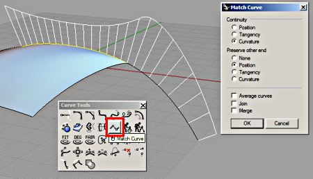
From the screenshot shown above, we can see that the Curvature Graph displays a better flow with little or no sudden break or transition.
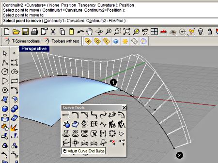
Next, we can bring up the Adjust Curve End Bulge tool to fine tune the curve. Make sure that the side (as indicated as 1 in the screenshot below) has Continuity = Curvature at the command line/prompt. For the other end (indicated as 2 in the screenshot below), in our case here, Continuity = Position is to be set. This is because we have only created enough control points for curvature to one end of the curve.
Once we are satisfied with this curve, we can proceed to create the other curve to match the other surface edge. Use the same method as described to ensure curve is curvature-matched to the edge as well. See illustration below of the other curve.
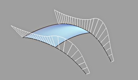
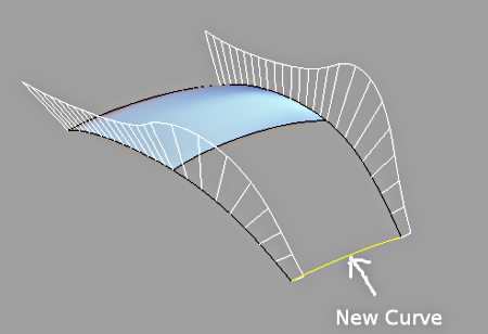
Now, we can use a surface tool with continuity to create the surface. In this case here, a new curve is created as shown below. The control point is turned on to adjust the profile to give it a slight bulge.
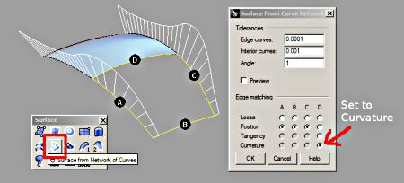
Next, using Surface from Network of curve, create the surface. Remember to set the Edge matching option to Curvature at the Options dialog. In this case, this is indicated as edge D. This is very important as surfaces do not automatically become curvature-matched even though the curves used to create them are.
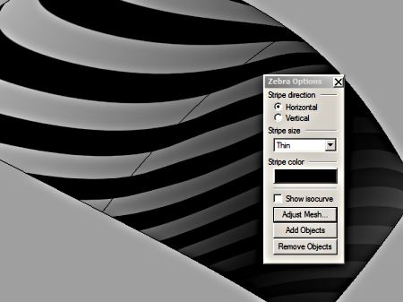
Use the Zebra tool to evaluate the surface continuity. Zebra strips can be used to indicate whether surfaces are position, tangent or curvature to each other. However, we are not going to go into the details here. Please note that the zebra tool cannot detect higher end continuity that can be seen by a curvature graph display.
What we have illustrated here is just a simple example. If we have additional adjacent surface edges to match to, the surface from network of curve tool can provide surface continuity matching options for all sides of its boundaries.
To purchase Rhinoceros Surfacing Techniques Book via Amazon, click on book cover image below.
Note: This tutorial is not part of the book.
Well, that’s all for this article. Thanks for reading 🙂
About the Author: Being an industrial designer by profession, I have done much technical modelling projects for clients such as Razer and Creative Technology. I am proficient with Aliasstudio, Pro-Engineer and Rhinoceros 3D.
Disclaimer: We are in no way to be held responsible if the results is not as desired by you.


Is there any samples to download and open them because i wanna see how i do it. 🙂 please reply
Sorry RhinoStarter,
I did not save the Rhino file.
Thank you fo the tutorial,
my question is: the created surface has the curves in g2 continuity at the edges, but if I analyze the continuity in the middle (with an isocurve extraction, or projection of curves) it is g1. Is it normal?
Hi Gulli,
The Edge matching option of the Network surface tool or Match surface command should be set to Curvature as well.
Regards